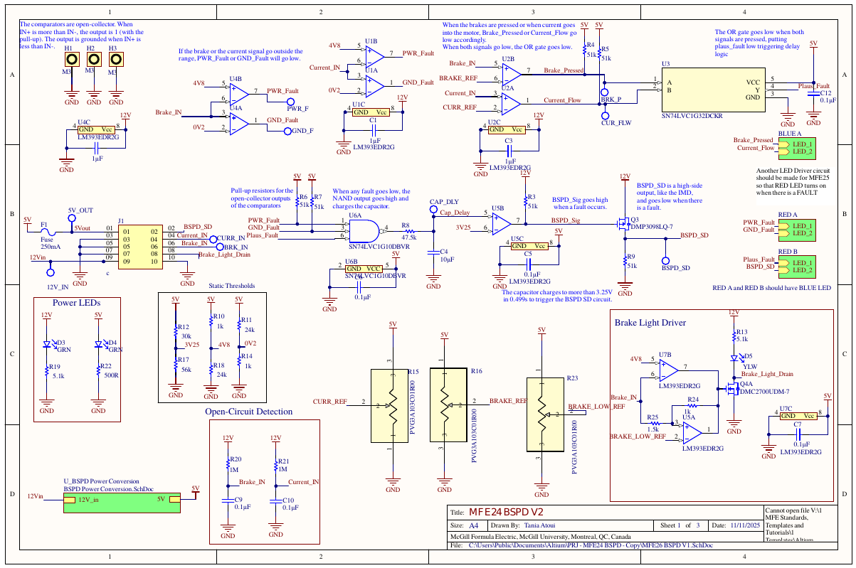
BSPD
The BSPD is the rules-mandated, non-programmable circuit that shuts the car down when brake and throttle are commanded simultaneously. Brake position comes from a pressure sensor on the brake line; throttle is inferred from accumulator current measured by a sensor in the HV bay. No firmware anywhere in the chain; the rules require the logic to be non-programmable.
Dual open-collector comparators pull to ground when tripped, giving the whole board active-low logic. Three fault classes, all terminal:
Power fault: either sensor above 4.8V. A sensor railing high is a sensor you can't trust. Ground fault: either sensor below 0.2V, broken wire, short to ground, dead sensor. Plausibility fault: the actual purpose, brake past its reference and current past its reference simultaneously drives the OR gate low.
Any asserted fault sends NAND U6 high and starts the rules-mandated delay: an RC charges toward the 3.25V threshold, arriving in ~500 ms. Transient faults discharge harmlessly; a held fault fires BSPD_SD and opens the shutdown circuit.
Rules define "brake pressed" as 25% of the sensor's max-pressure output, and the throttle threshold as the current delivering 5 kW at nominal pack voltage. Those numbers move year to year, so the brake and current references sit on 10k potentiometers, retune with a screwdriver instead of a soldering iron. The power/ground fault dividers are static because sensor rails don't move.
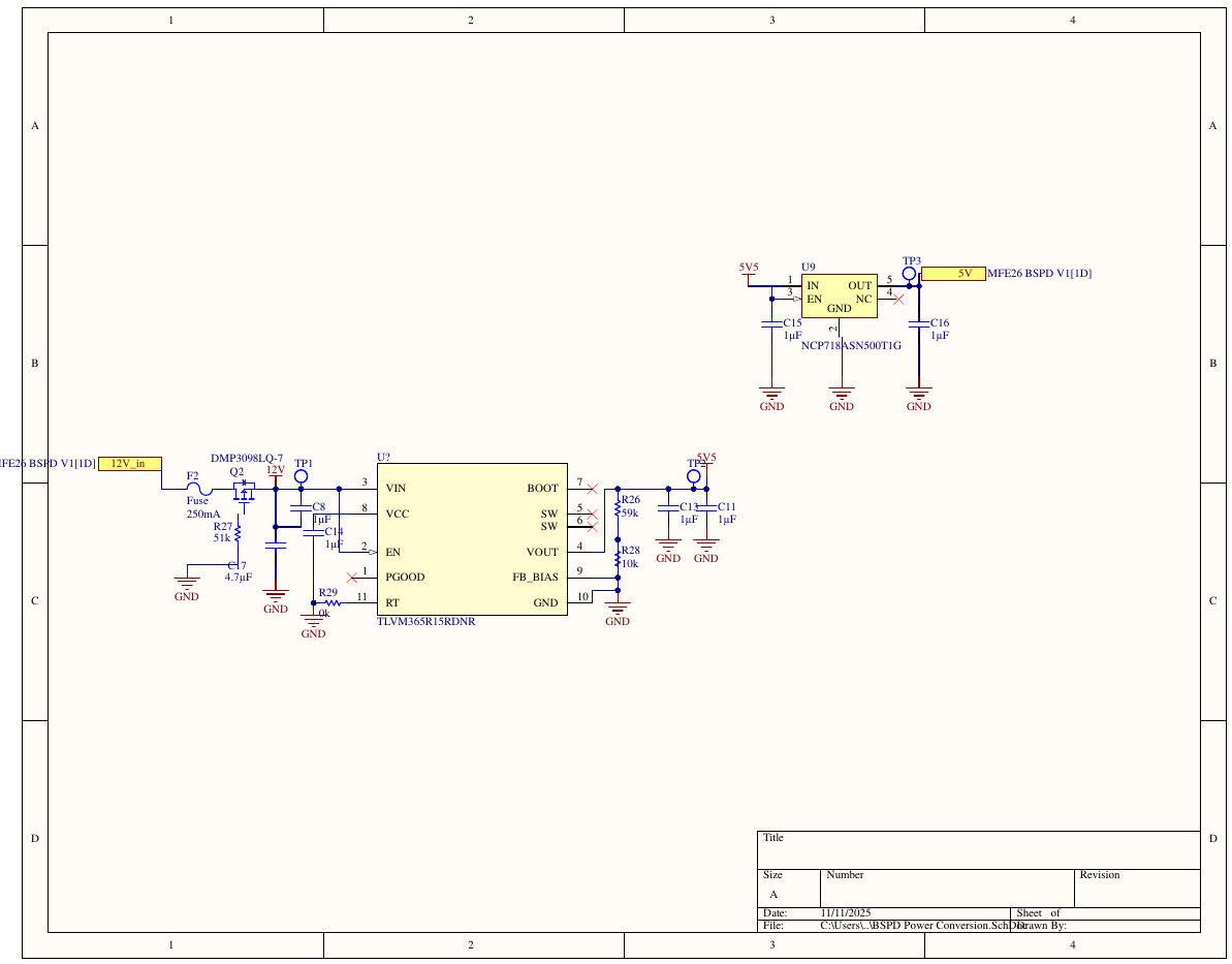
12V from the fuseplane comes in behind reverse-polarity protection (a series P-FET that only conducts with correct polarity), steps down through a TLVM365 buck module to 5V5, and an NCP718 LDO cleans that to the 5V analog rail, buck for efficiency, LDO so the comparator references sit on a clean rail. The brakelight driver is a low-side switch on its own window comparator: while Brake_IN sits above the pot-set BRAKE_LOW_REF and below the 4.8V rail, Brake_Light_Drain pulls low and the brakelight board's LEDs fire.
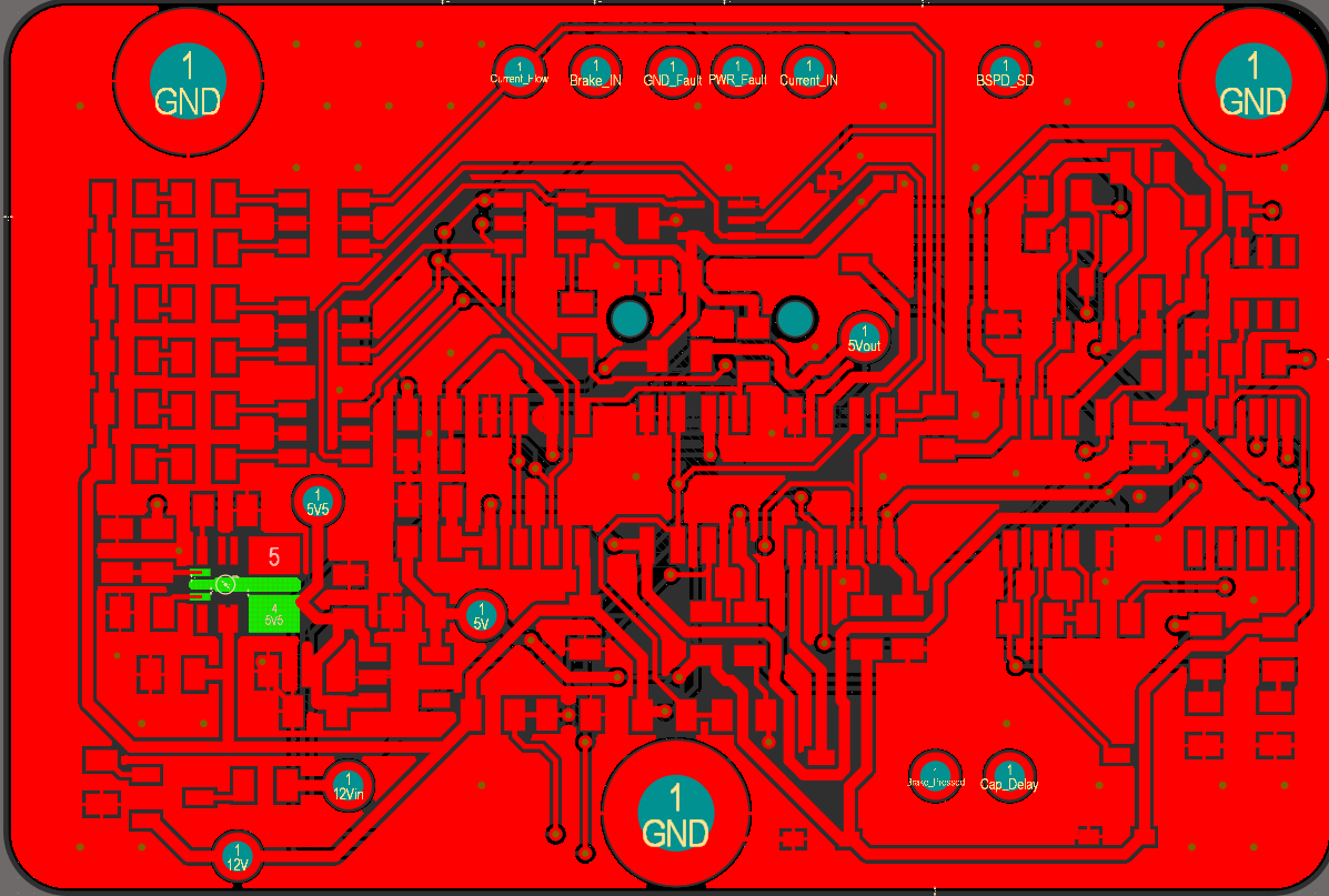
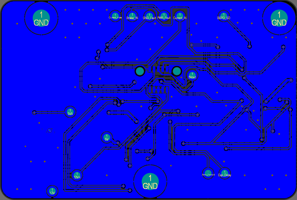
Every node that matters is on a labeled test point, Brake_IN, Current_IN, each fault line, Cap_Delay, BSPD_SD, and the full power chain (12V, 12Vin, 5V, 5V5, 5Vout). You can characterize the whole fault tree with one probe and no schematic open.
The whole fault tree on one sheet: LM393 open-collector comparators against the 0.2V / 4.8V rails and the pot-set BRAKE_REF / CURR_REF, into the OR gate (SN74LVC1G32) for plausibility, the 3-input NAND (SN74LVC1G10), and the RC delay that trips BSPD_SD through the high-side P-FET at 3.25V (~0.5 s). The brake light driver rides along with its own window comparator on BRAKE_LOW_REF.
My first layout. What held up: labeled test points on every fault line, both sensor inputs, the delay cap, and the full power chain, so the board can be characterized with one probe and no schematic open; and all safety logic in analog hardware. What I'd redo: routing on both outer layers cut into the ground pours, patched with stitching vias. That's acceptable at these signal speeds, but the LVBMS got dedicated internal planes as a direct result.