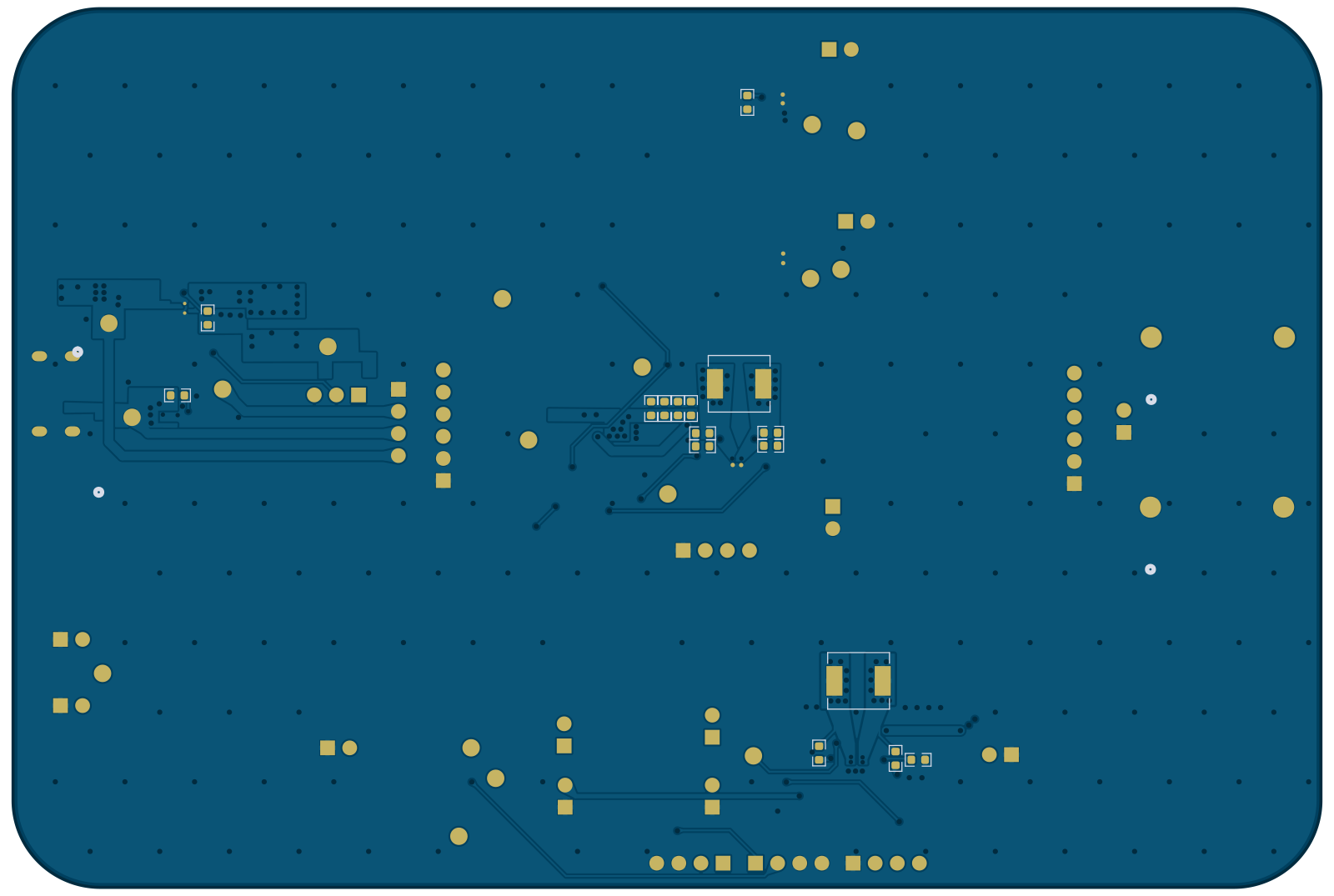
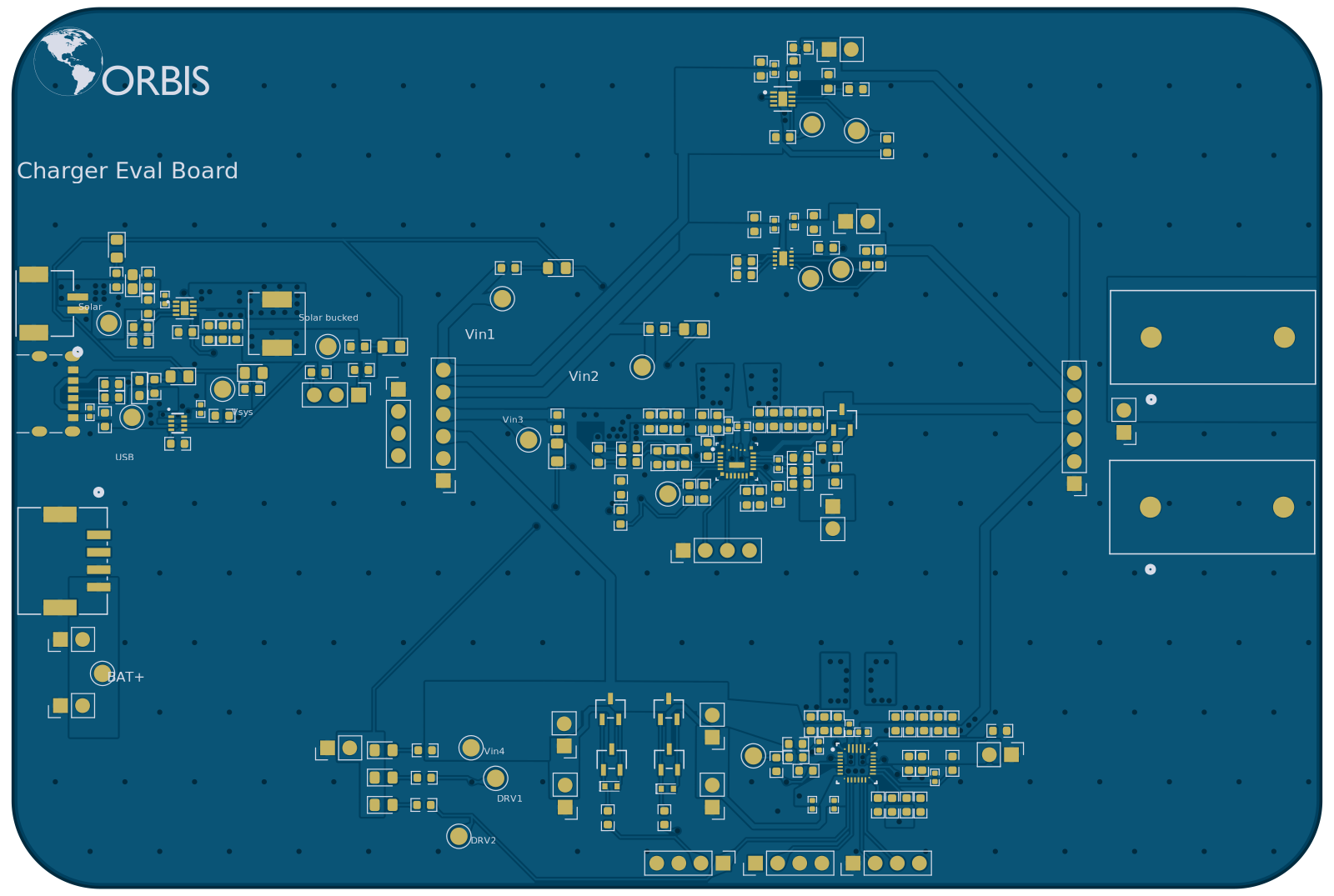
Charger eval board
The flood gauge sits outside all winter, so the cell inside it matters. LTO takes a charge in the cold and puts up with deep cycling, but it costs more and sits at a lower cell voltage. LFP is cheaper and denser, but charging it below freezing plates lithium and kills the pack. This board settles that in a cold chamber instead of on paper.
Power comes in on the left. There are three inputs: a solar panel, USB, and a bench supply for controlled tests. The solar leg goes through a TPS62125 buck first, so a panel that swings all over the place lands somewhere usable.
All three then hit an LM66200 dual ideal diode, which passes whichever input is highest and blocks the rest. That output is Vsys, and it feeds everything downstream.
From Vsys, jumpers pick which charger gets the rail. There are four of them on the board, so one cell can be run against every topology without cutting a trace or spinning a new board. Whichever charger is jumpered in charges the cell.
The cell then breaks out to an electronic load. Charge it, discharge it, do both at temperature, and you get a real capacity number instead of a datasheet one.
| Part | Type | Why it is on there |
|---|---|---|
| LTC4079 | Linear | Very low quiescent current, the baseline for a solar trickle charge |
| BQ25173 | Linear | Cheap and simple, sized for the low-current LTO case |
| BQ25690 | Buck-boost | Keeps charging when the panel sags under the cell voltage |
| BQ25798 | Buck-boost, MPPT | Most current, and the only one that actually tracks a panel |
- Two layers, 150.3 × 101.0 mm, with a ground pour on both sides and 303 vias stitching them.
- The charger sense resistors are routed Kelvin on SRP and SRN. On two layers with a shared pour that is the difference between a current reading and a guess.
- Input caps on the buck-boost slots are split across two banks so the switching ripple stays off the shared Vsys rail and out of the other three chargers.
- Both buck-boost slots use the same TDK SPM6530T inductor footprint, 1 µH and 4.7 µH, so the parts swap during bring-up without a rework.
- A ferrite bead on the VBUS entry keeps switching noise from walking back out of the fixture.
First board came up with the fuel gauge dead. The protection FETs had latched off, so the gauge never enumerated and the charger saw no cell at all.
Overriding the FETs in TI BQStudio woke it up and let the rest of the board get characterized instead of waiting on a reflow. That became step one of the bring-up procedure for the rest of the units.