TSIL + RTM LIGHT BARS
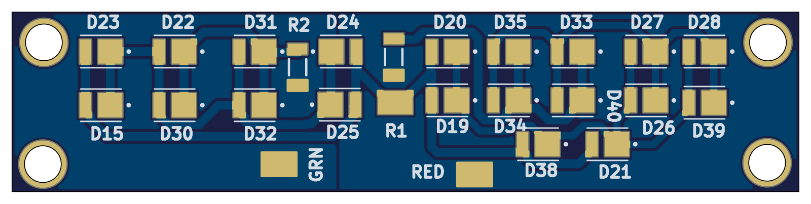
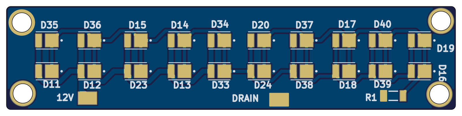
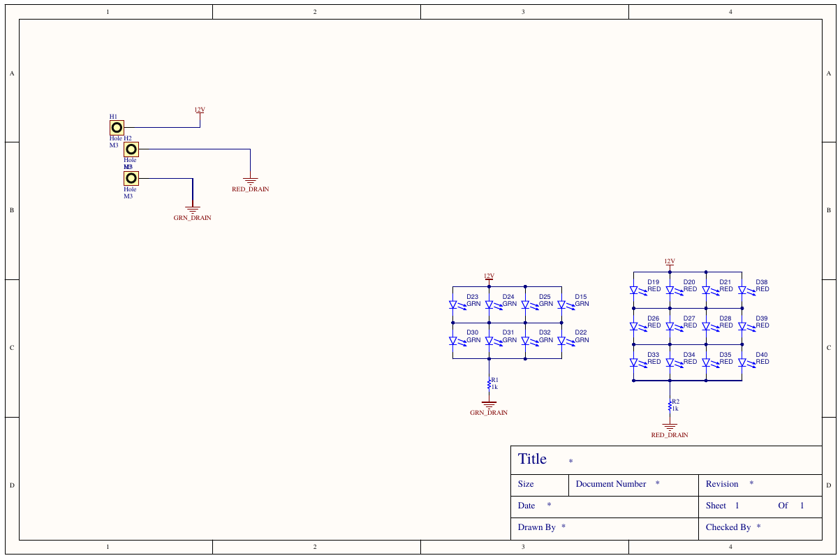
The lights themselves. The TSIL bar carries two interleaved LED sets: green LEDs that hold steady while the system is healthy, and red LEDs the driver board flashes on its 555 clock when a BMS or IMD fault is live. The RTM bar flashes on the driver's ready-to-move output.
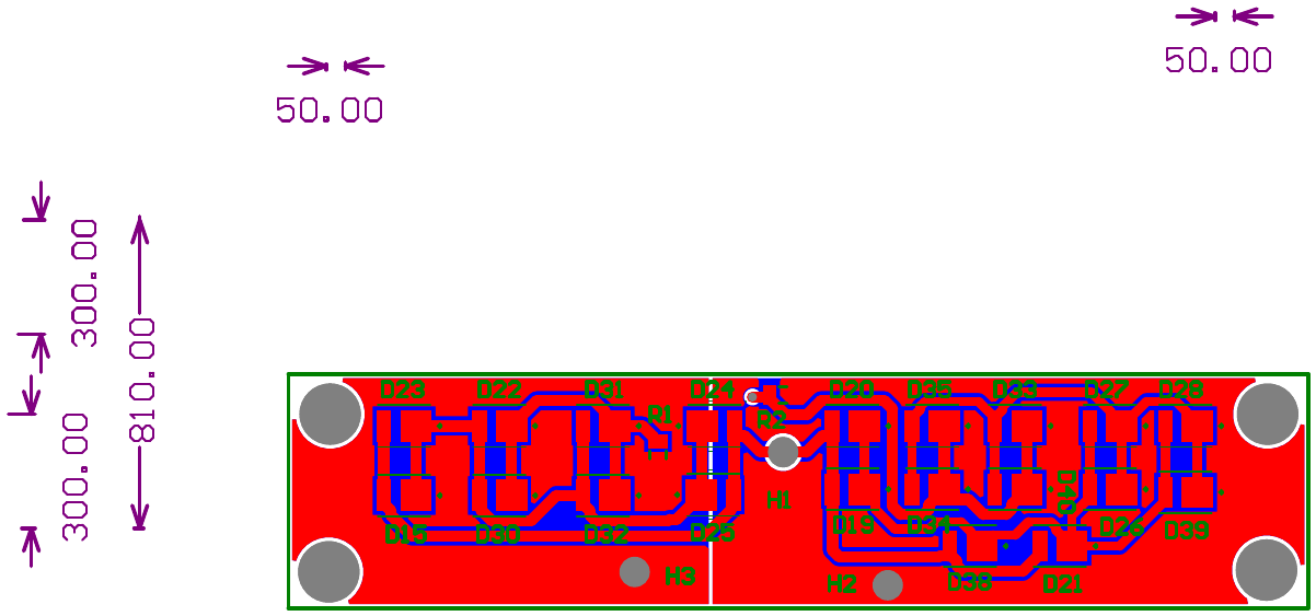
Continuous LED current means continuous heat, and a metal-core PCB conducts it out through the substrate instead of cooking the junctions. The tradeoff: aluminum-core boards can't take plated through-holes without expensive insulated-via processes, so both bars are routed entirely single-sided, zero vias, with trace widths sized for the LED string current.
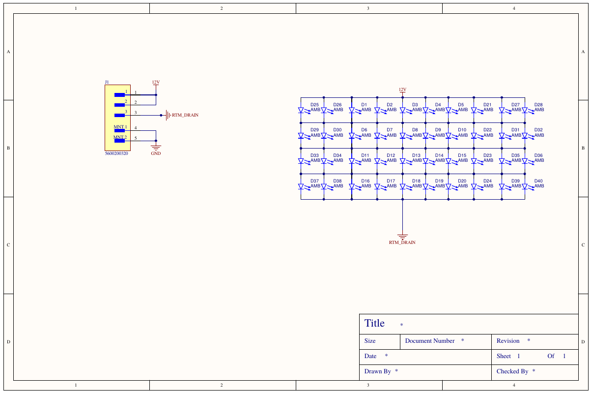
TSIL bar: two interleaved LED matrices, 8 green always-on when healthy, 12 red on the driver's flashing drain, plus the RTM bar: 40 amber LEDs in a 4×10 matrix on a single low-side drain. Both single-sided on aluminum core.
RTM bar sheets:
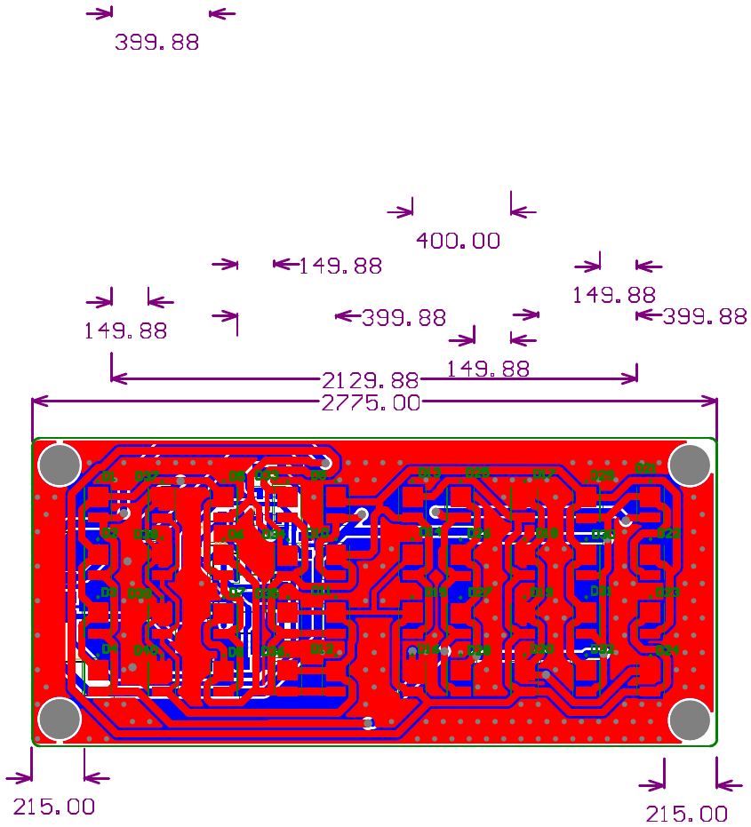
Metal-core boards can't take plated through-holes without an expensive insulated-via process, so both bars are routed entirely single-sided and the aluminum substrate handles the heat. All logic stays on the driver board; a damaged bar trackside is a plug-in replacement, not a debugging session.